In technology, instruments are widely used to measure the magnitude of displacements of objects with their conversion into electrical signals. The potentiometric sensor in most designs is a rheostat and a sliding contact connected to the object, from which the signal is removed. The output parameter is the value of electrical resistance, depending on the angular or linear movement of the movable element.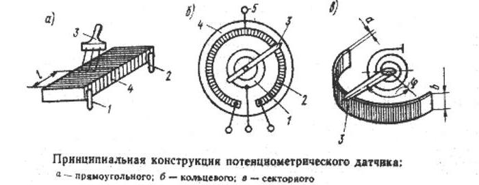
Operating principle
The potentiometer converts linear or angular displacements to the appropriate voltage, current or resistance values. Due to this, it is possible to work with many non-electric quantities: pressure, level, flow rate, etc.
Potentiometric sensors, the principle of which is to measure the displacement or location of the position, are connected by their movable contacts of the variable resistor to objects. It can be valves, antennas, cutting tools and much more. After supplying power to the sensor, the signal of the position of the potentiometer slider is removed from it, as with a voltage divider.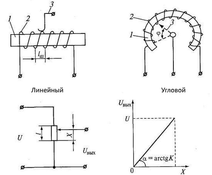
The basic registration method in all models remains the same, but there are structural differences. The signal can be taken directly or using an electronic circuit after its processing and normalization. It is important that it meets certain standards.
Advantages of potentiometric sensors
- Simplicity of design.
- Low cost.
- Good resolution.
- Compact and light weight.
- The stability of the readings.
Design
Potentiometric wire motion sensors are common in industry. They have high accuracy and stability, have small values of temperature and transition resistance and a low noise level. The disadvantages include: a small amount of resistance, low resolution, wear of moving parts and limited use when working on alternating current.
Devices consist of three main elements:
- Wireframe. Made of heat-conducting insulating material or dielectric coated metal, which does not change geometric dimensions when heated. The shape may be in the form of a ring, a curved plate, a rod.
- Insulated winding. It is carried out with the exact laying of the wire, on the step of which the resolution of the device depends.
- Movable brush. In places of its contact with the winding, the turns are cleaned of insulation. The movable contact in the devices can move translationally or rotationally. In the latter case, the devices can be single or multi-turn execution.
Materials
The frame is made of dielectric material: ceramics, getinaksa, textolite, plastic. Apply metal with an insulating coating. Its high thermal conductivity makes it possible to well remove heat from the sensor wire.
The metal of the winding has a high electrical resistivity, corrosion resistance, a slight temperature effect, abrasion and tear resistance. Manganin, constantan, nickel-chrome alloys meet these requirements. Winding can also be lamella or film.
Sliding contacts reduce the reliability of the sensors and complicate the design. Disadvantages of wire potentiometers:
- low reliability of contacts;
- instability of the transition resistance between the motor and the winding due to oxidation and electroerosion of the wire;
- bounce of contacts.
Conductive plastics, which also have better linearity, have a great resource.Sensors based on them are used where high reliability is required, especially in aviation.
Contact brushes are made with the addition of noble metals so that they are softer than the material of the winding.
Scheme
Potentiometric type sensors have a static characteristic - output voltage Uout from moving contact X. The relationship between these parameters in an unloaded potentiometer is usually linear:
Uout = kX,
where L is the length of the sensor, k is the sensitivity (k = UPete/ L).
In reality, the potentiometric sensor contains a load resistance Rn in the next link of the automatic control system, which affects the value of Uout
The low reliability of the sensors associated with the loss of contact, open circuit winding or interturn circuit, leads to the need to change the wiring diagram.
If the sign of the output signal does not change, the sensor is called unipolar. It is a simple device like a variable resistor.
A push-pull type potentiometric sensor circuit is used for automatic control, where the sign of the signal changes at the output, depending on which input it is. The direction of the control movement of the working body depends on this. 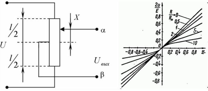
The voltage can be removed from the brush and from the middle of the potentiometer. Other wiring diagrams are also used. When powered by direct current, when the movable contact passes through its midpoint, the sign at the output changes to the opposite. If AC voltage is applied to the winding, the phase changes by 1800.
In automation, non-linear characteristics of the sensors are used. For this, the diameter of the wire along the winding, the step of the winding changes, complex-shaped frames are used, sections of the potentiometers with resistances are shunted.
Operational characteristics
The idle response of the sensor is a straight line (R / Rn = 0). The deviation of the curves from it increases with decreasing load resistance Rn.
In addition to active resistance, sensors also have dynamic loads:
- Transmission function.
- Inductive component.
- Own noise during the transition of the moving contact from coil to coil and from brush vibration.
The resistance between the contact of the engine and one of the conclusions is called the output. Its magnitude, current or voltage is measured.
Sensor errors
The following errors affect the actual characteristics of the sensors:
- Dead zone. When the contact passes from one turn of the wire to another, a voltage jump occurs, the value of which is determined by the formula: DU = UPete./ W, where W is the number of turns.
- The unevenness of the static characteristic associated with fluctuations in the diameter of the wire along the length, its resistivity and accuracy of winding.
- The presence of play between the contact motor and the sleeve, which affects the accuracy of the readings.
- Uneven brush pressure, affecting the value of contact resistance. Usually, the force of pressing the engine to the winding is used quite large. However, this is not always possible to do, because the force from the sensitive elements (membranes, floats, bimetal plates) is small.
- The effect of electrical load resistance Rn. Its value is chosen 10 ... 100 times more than the resistance of the sensor.
Appointment
The potentiometric position transmitter is designed for the following purposes:
- control and measurement of movements of mechanisms, working bodies of machines and other objects;
- feedback link in robotics and automation systems;
- determination of distances to objects;
- tests in laboratories, monitoring the operation of mechanisms.
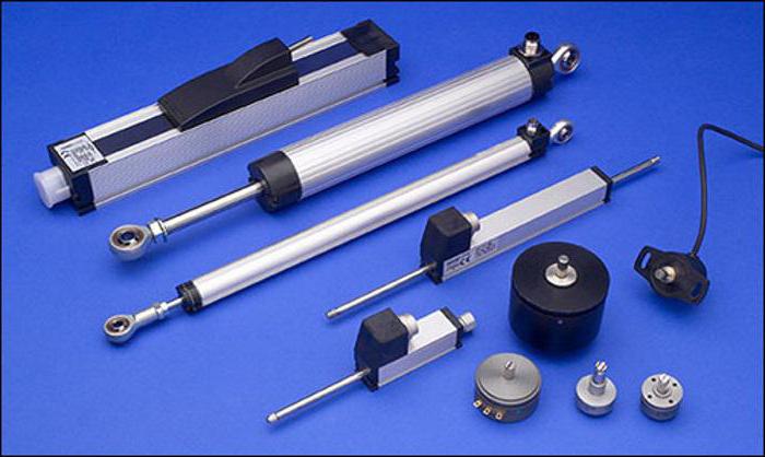
Sensor Types
The use of a potentiometric sensor depends on the type:
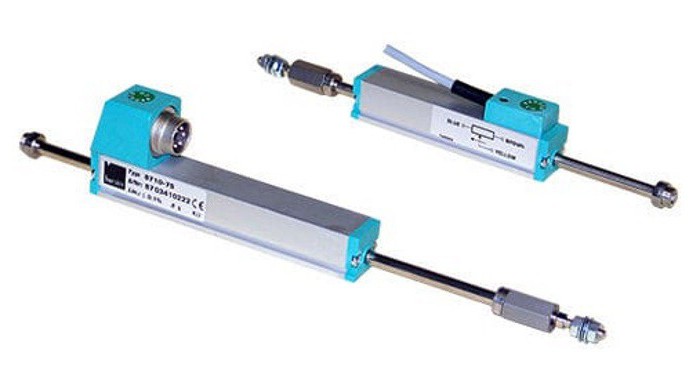
- T / TS is a high-precision instrument (0.075%) operating in the range of axial displacements of 150 mm. Suitable for peripheral speeds up to 10 m / s. Design - ensuring the movement of the rod in two directions according to the principle of a voltage divider.
- TR / TRS - the same as the previous one, but with a return spring. Displacement reaches 100 mm. Withstands higher lateral loads at the tip.
- TE1 is a model that contains an electronic circuit for normalizing signals with an analog output.
- TE1 with return spring - modification for solving a wider range of tasks. The sensor is more stable with increased lateral loads.
- TEX is a potentiometric sensor with a swivel head and tracking linear movements of objects up to 300 mm. The swivel joint facilitates installation and ensures a long service life.
- TEX with a threaded drive rod. It makes it possible to rigidly fix an object.
- TEX with a return spring does not require rigid attachment of the object to the bar.
- TX2 with swivel head or with mounting clamps. They are used in severe operating conditions. The level of protection is IP 67, accuracy - 0.05%.
The use of potentiometers in pressure sensors
The operation parameters of various devices are conveniently converted into electrical signals. A potentiometric liquid or gas pressure sensor is used in fuel supply systems in cars, gas in highways, etc. Usually these are membrane measuring devices.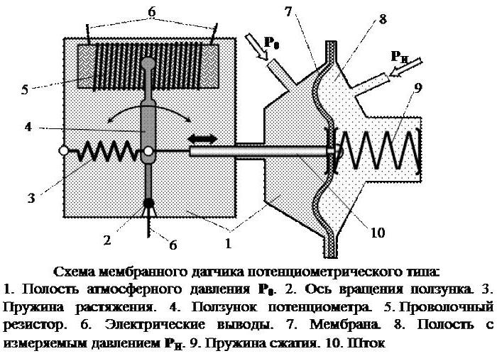
Under the action of a pressure differential on both sides of the membrane, it moves. At the same time, the slider also rotates. If the pressure P0 and Pand are equal to each other, the engine goes to its original left position, at which the initial resistance of the device is set. When pand decreases, the membrane moves to the right, and the slider sets the potentiometer brush to the position corresponding to the pressure drop.
To reduce the error of a discrete change in the resistance of the potentiometer, the number of turns on it is made at least 100. It can be completely eliminated by moving the brush along the axis of the calibrated rechord wire.
Sensor Designs
The potentiometric linear displacement sensor consists of a dielectric frame of various shapes (plates, cylinders, rings, etc.), on which an insulated wire is wound, attached to the clamps and secured with clamps at the ends. A metal brush moves along the winding. For sensors of a rotary type, the frames are ring-shaped, longitudinal - straight. In places of contact with the engine, there is no insulation on the wire.
The terminals are powered. The output signal is taken between one end of the wire and the brush contact, although there are other connection schemes.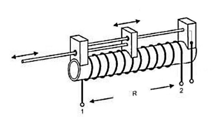
Each linear potentiometric sensor has a static characteristic in the form of a dependence of the value of the output signal on the displacement of the brush contact.
Conclusion
The potentiometric sensor must be reliable, convenient and durable when used in measurement technology and in automatic control systems. Devices for monitoring the position of objects differ in principle of operation and in the types of output signals, which must comply with standards.