In construction and industry, welding operations are common, allowing you to assemble durable structures and mechanisms of varying degrees of complexity. At the stage of monitoring the resulting seam, it is not always possible to assess the reliability of the connected assembly within the structure. For this, non-destructive methods of testing welded joints are used. The radiographic method of analysis is one of the most common in this niche.
The principle of operation of radiographic control
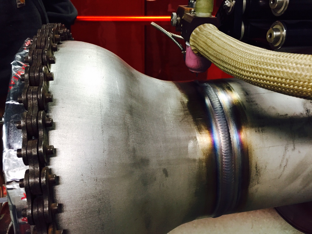
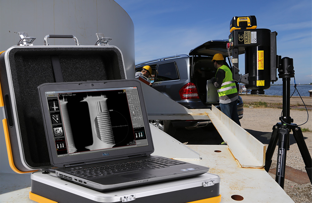
The method is based on the use of radioactive radiation, which allows analyzing the internal structure of the material without physical intrusion with deformation. For this, x-rays and gamma rays passing through the product are used. As a result, the operator receives a map of structural defects recorded on a magnetographic film. Radiation allows you to form an image with hidden contours of the structure, the decryption of which is performed on a special developer in the process of photo processing. In each case, the parameters for performing radiographic inspection of welded joints according to GOST 23055-78 may vary - up to 6 in diameter and from 1 to 10 mm in length with respect to pores and lack of penetration. If the length of the overall radiogram is less than 100 mm, then the total area of defects decreases in proportion to the length of the card. The penetration depth of x-rays is determined by the parameters of the part.
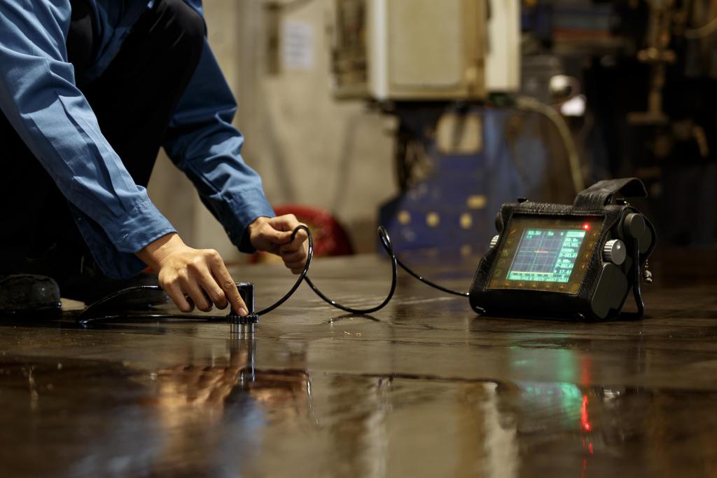
The technology of radiographic control is often used together with the ultrasonic method of analysis of the structure of materials. Such a combination usually occurs in situations where the use of ultrasound is not technologically possible. In addition, beam scanning provides more information about the geometric data of pitting and corrosion lesions. Differences in ultrasonic and radiographic inspection of welded joints relate to the effectiveness of the study of defects with different shapes. In the first case, automatic ultrasonic flaw detection is more likely to focus on working with plane flaws in the form of imperfections and cracks. In turn, radiography gives high accuracy of the analysis of volume defects.
Appointment of radiographic control
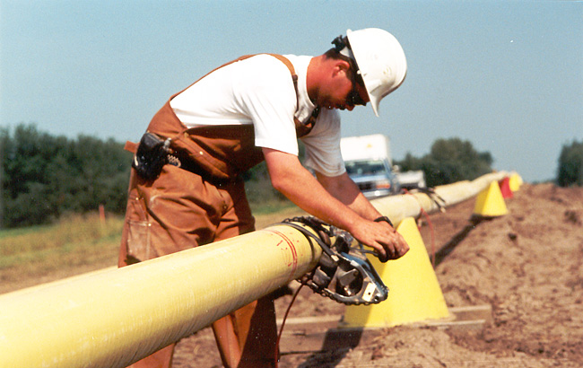
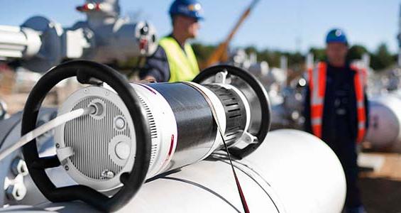
This control method is used to assess the quality of a welded joint of metals and alloys, the thickness of which varies from 1 to 40 cm. Defects are determined mainly in the internal structure of products in the conditions of local absence of foreign inclusions, technological pores and solder. Also, according to GOST, welded joints at the time of inspection should be rid of slag, melt spatter, scale and other impurities left during the welding process. The most common area of application for radiographic monitoring is onshore and underground pipelines. The analysis is performed by directing the rays into the pipe using flaw detection equipment. As applied to underground utilities, this scanning method is advantageous in that it does not require opening channels with earthwork.
It is worth highlighting the situations in which the use of radiographic control is ineffective or not allowed at all due to technical and structural limitations:
- Various kinds of inclusions and discontinuities, the size of which in the direction of transillumination is smaller than the doubled sensitivity of the control.
- Inclusions and discontinuities that are close to sharp corners, differences or third-party parts provided for technologically. In the radiogram images, the coincidence of defects and structural elements will not allow to accurately determine the characteristics of the internal structure.
- Cracks and lack of fusion, in which the plane does not coincide with the lines of transmission. In this case, a combination of radiographic scanning with destructive testing elements can be used.
Types of used radiometric devices
To date, the following types of equipment for radiographic monitoring are actively used:
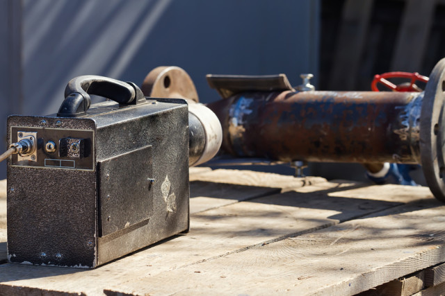
- Devices with a constant frequency of gamma radiation with a fixed intensity. Deviations in frequencies cause product defects, which is reflected in the radiograms. The latest models of such devices are provided with programs that accurately determine vibrational spectra.
- X-ray equipment with support for high-frequency fluctuations, random in time. The degree of fluctuation depending on the radiation intensity can exceed 0.5-1%.
- Devices for radiographic inspection of welded joints, the stability of gamma radiation of which exceeds 0.5%. In this case, the oscillation amplitude is within 0.1 Hz. Such equipment is optimally suited for thin scanning of small volume defects, but it is not practical to use it in the analysis of deep flaws in large areas.
In terms of controls, almost all devices support automated tools with the ability to programmatically adjust the received data when generating radiograms.
Preparation for radiographic inspection
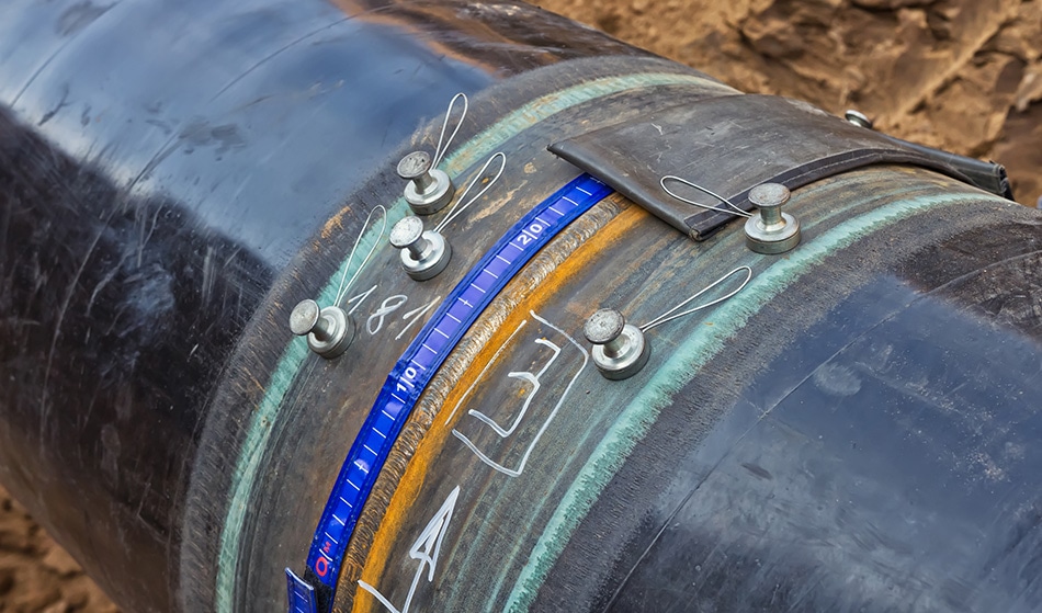
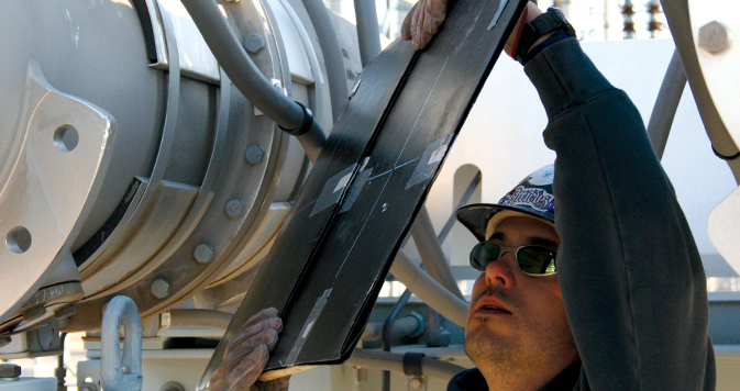
Before scanning, special attention is paid to the condition of the product and directly to the weld. The operator inspects the part to identify external defects, removes impurities and, if necessary, marks the areas. Large areas for scanning are marked by zones and numbered without fail. Further, standards with sensitivity marking are set in controlled areas. For example, groove standards should be placed 5 mm from the seam line with a transverse direction. To achieve the most reliable result when controlling the quality of welded joints, cards from previous studies can be used. They are prepared in advance and entered into the equipment radiogram system before scanning. Images of new images will be formed with an emphasis on previous data. The software also directs graphic scanning to account for existing defects, providing a separate layer of information on the degree of progress of the same discontinuities, cracks and lack of fusion.
Determination of control parameters
After preparing the product, the optimal characteristics of its examination by the scanning apparatus are selected. One of the important parameters will be the distance from the source of gamma radiation to the surface of the target area, as well as the number and size of the controlled areas. According to GOST, welded joints are scanned by radiographic equipment under the following restrictions:
- The increase in the size of structural defects that are located on the side of the radiation source apparatus should not be higher than the coefficient of 1.25.
- The angle between the normal to the photographic film and the direction of gamma radiation should not exceed 45 ° when examined within one controlled area.
- Blur image defects when placing the film for pictures close to the weld should not be higher than half the established degree of sensitivity.
- The length of the images during radiographic inspection of welded joints should capture images of adjacent sections in accordance with the marking.If the length of the controlled area is within 100 mm, then the overlap is at least 0.2 of the total length of the plot, and if it is a distance of more than 100 mm, then the grip should be at least 20 mm.
- In the event that the dimensional parameters of the defects are not determined, the requirements for maintaining the ratio between the outer and inner diameters of the joint can be ignored.
Schemes of radiographic inspection of welded joints
The effectiveness of the control is determined by the transmission pattern of the product structure. So, in the process of scanning annular seams of spherical and cylindrical parts, transillumination through the wall of the element is usually used. Moreover, the source of radiographic radiation is located inside the product, which allows you to more accurately fix the map of defects. If the diameter of the cylindrical hollow part does not exceed 2 m, then radiographic inspection of welded joints with panoramic schemes is used. But it is important to keep in mind that selective zonal analysis of the internal structure in this case will be impossible.
In the process of scanning butt joints, the direction of transillumination coincides with the plane of the examined area. Such a scheme is used in working with angular knots of penetration of fittings and pipes. The angle between the radiation and the junction plane should not be higher than 45 °. In addition to standard configurations, other directions of defect transmission are also used.
When choosing a scheme for the radiographic method for controlling welded joints, the distance from the target analysis surface to the film of the apparatus (not more than 150 mm) and the exposure of a 45-degree angle in the direction of radiation are taken into account. Correctly selected tactics of imaging will provide an informative and accurate map with defects in the problematic product.
Decoding radiographic images
Viewing images is organized in a dark room after drying with the help of illuminators-negatoscopes, which allow you to adjust the brightness and parameters of the illuminated field. In this case, special requirements are placed on the quality of materials:
- No streaks, stains, damage and contamination on the surface of the emulsion layer. Anything that makes decryption difficult should not be in the picture.
- In addition to the contours of defects, markings, marks and boundary structural lines, if any, should be reflected.
- The optical density of the graphic card generated during the quality control of welded joints in the area near the seam should be at least 1.5.
Image processing can also be carried out on scanning computer equipment with the generation of defect models. In this case, the accuracy of determining the location and size of damage in the structure increases.
Separation of types of welded joints according to the results of control
According to the results of the data in the pictures, each seam is assigned a particular class depending on the size of the defect. According to regulatory requirements, the classification is based on pore sizes, as well as oxide, slag and tungsten inclusions. For example, with a product thickness of up to 3 mm, it is supposed to be divided into types of welded joints, depending on the total length of the defect - from 3 to 10 mm. If we are talking about parts with a thickness of 200-400 mm, then the classification range for the same parameter will vary from 10 to 90 mm. Again, if the length of the radiogram is less than 100 mm, then the calculated data on the size of individual inclusions and pores are reduced in proportion to the size of the image. Moreover, the length of the clusters in accordance with the requirements should not exceed 1.5 relative to the maximum permissible lengths for individual pores and discontinuities.
After processing the materials of radiographic control, a special act is drawn up, which indicates the data on the product and the defects it contains.First of all, the characteristics of the part or structure are described with the indication of previously designated standards and marked areas. Radiographic inspection of welded joints may include data on capacity, product thickness, and other technical and structural indicators. As for information on defects, the entire list of information obtained as a result of decoding of radiographic images is entered in special columns.
Radiographic safety precautions
The greatest danger when performing a radiographic scan is caused by gases released by gamma radiation. To begin with, it is worth emphasizing the importance of control conditions that must meet the requirements for the use of radioactive sources. The electrical equipment used must be in good condition and, if possible, tested immediately before the analysis of the welded joint. Industrial radiography is subject to increased requirements in terms of ensuring electrical safety. This applies to situations of using powerful stationary devices that are connected to three-phase power networks. Without fail, voltage stabilization means and short-circuit protection units are introduced into the infrastructure.
Pros and cons of radiographic monitoring
Radiography gives quite wide possibilities of flaw detection of welds, allowing with high accuracy and convenience to analyze the tiniest flaws in the structure of metal structures. Images on radiography images are as close as possible to optical, so they can be analyzed not only by flaw detectors, but also by the welders themselves. To interpret the results, special atlases with classifications are issued, according to which you can easily give a quick assessment of defects. As for the disadvantages of radiographic inspection of welded joints, they include sensitivity to the detection of planar discontinuities and low reliability when scanning imperfections and cracks. To this we can add the presence of radiation and high financial costs associated with the use of sophisticated equipment at almost all stages of control.
Conclusion
At the moment, radiography is, although not the most attractive in terms of operational advantages, but a very convenient and effective way of non-destructive testing of welds. Suffice it to say that in the energy sector, radiographic control of welded joints of pipelines occupies about 30% of all cases of analysis of trunk lines for the detection of defects. The closest competition to this method is ultrasonic testing. However, factors such as the need for technological upgrade of enterprises with the replacement of expensive equipment and the limited scanning capabilities of ultrasound still impede the complete crowding out of radiography. Therefore, in some areas, radiographic monitoring remains indispensable.